Setting up the Juice Shop Lego Tower
The Juice Shop Lego Tower is a cluster of Raspberry Pis configured to run MultiJuicer for local hacking events. This guide explains how to set up the tower including the network and WiFi configuration.
|
|
|
Hardware Parts List
The following hardware is used for the Lego Tower. Note that this is just a sample setup and other equivalent hardware will do just as fine.
-
TP-Link Archer C6 ("WiFi router")
-
TP-Link TL-MR3020 N300 Nano ("WISP router", optional)
-
TP-Link TL-SG1005P 5-Port PoE Switch ("PoE switch")
-
4x Raspberry Pi 4
-
4x Raspberry Pi 4 PoE+ HAT
-
4x SD card 16GB
-
4x 0,5m Ethernet cable Cat5e
-
2x 1m Ethernet cable Cat5e
|
One of the two 1m cables might have to be longer: For the WISP setup 1m is totally sufficient, but for the LAN setup you might need a 5m or even 10m cable. Make sure to check the distance to the LAN socket at the venue beforehand and get a longer cable if needed. |
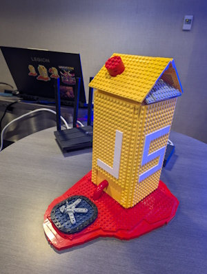
Lego Tower Assembly
For the physical construction of the tower, please refer to the following resources:

|
The Lego tower |
Local MultiJuicer Setup
This setup uses a cluster of Raspberry Pis and k3s as the Kubernetes distribution. For detailed information, see the official MultiJuicer Raspberry Pi guide.
Raspberry Pi Configuration
When following the abovementioned guide, apply these specific adjustments for the Lego Tower setup:
-
In Step 3b, use the IP address (obtained from your WiFi router’s Address Reservation) instead of the hostname for node communication.
-
In Step 5, install MultiJuicer with the following command to limit it to 40 instances:
helm install multi-juicer --namespace multi-juicer oci://ghcr.io/juice-shop/multi-juicer/helm/multi-juicer --set config.maxInstances=40 -
In Step 6, choose the configuration option without a DNS hostname and without a TLS certificate for local network use.
|
In this simple setup, MultiJuicer will only be accessible via the IP address of the primary Raspberry Pi (the one running the control plane). For a full-fledged DNS setup, additional steps are required as described in MultiJuicer Raspberry Pi guide Step 6. |
Network Infrastructure
The network for the Lego Tower consists of a WiFi router and an optional WISP router to ensure a stable and isolated environment for the participants. The WISP router is only needed when no Internet via LAN is available at the venue.
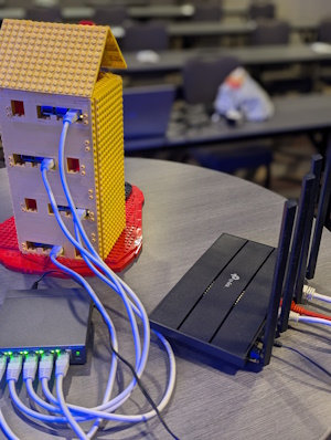
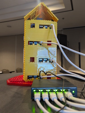
Network Cabling
The following schematic illustrates how to connect the network cables:
                      [ Venue Internet ]
                 (WiFi) <or> (LAN socket)
                 /             |
                /              | {≥1m cable}
               /               v
              v         (WAN port)
[ WISP Router ] <------> [ WiFi Router ]
              {1m cable}    (any of LAN1-4 port)
                               |
                               | {1m cable}
                               v
                       (Port 5 w/ one LED)
                        [ PoE Switch ]
                   (Ports 1,2,3,4 w/ two LEDs)
                         /   |   |   \
          {0.5m cables} /    |   |    \
                       v     v   v     v
[R1] [R2] [R3] [R4] (Raspberry Pis)-
The four 0,5m cables connect the Raspberry Pis with the ports
1to4of the PoE switch. -
The 1m cable connects any of the WiFi router’s ports
1to4(yellow) with the PoE switch’s port5. -
If using a WISP router, connect it to the WiFi router’s
WANport with the second 1m cable. Otherwise, connect the venue’s Internet LAN cable to the WiFi router’sWANport.
|
When connecting the power supply to the Wifi router and PoE switch, make sure to not mix up their PSUs! The WiFi router’s PSU is 12V/1A, while the PoE switch’s PSU is 53.5V/1.3A. Both unfortunately have the same plug size. Using the PoE switch’s PSU on the WiFi router will fry its circuits! The author has "successfully tested" this, so please be careful. |
WISP router (External Gateway)
The WISP router acts as a bridge between the host WiFi (e.g., at a conference) and the internal tower network.
-
Connect the WISP router to your laptop via a network cable.
-
Perform the Quick-Setup by navigating to http://tplinkwifi.net/.
-
Select the WISP mode and connect it to the host WiFi.
-
Once configured, disconnect it from your laptop and plug its LAN/WAN socket into the WAN port of the WiFi router.
WiFi router (Main Tower Router)
The WiFi router manages the internal network and provides WiFi for the participants.
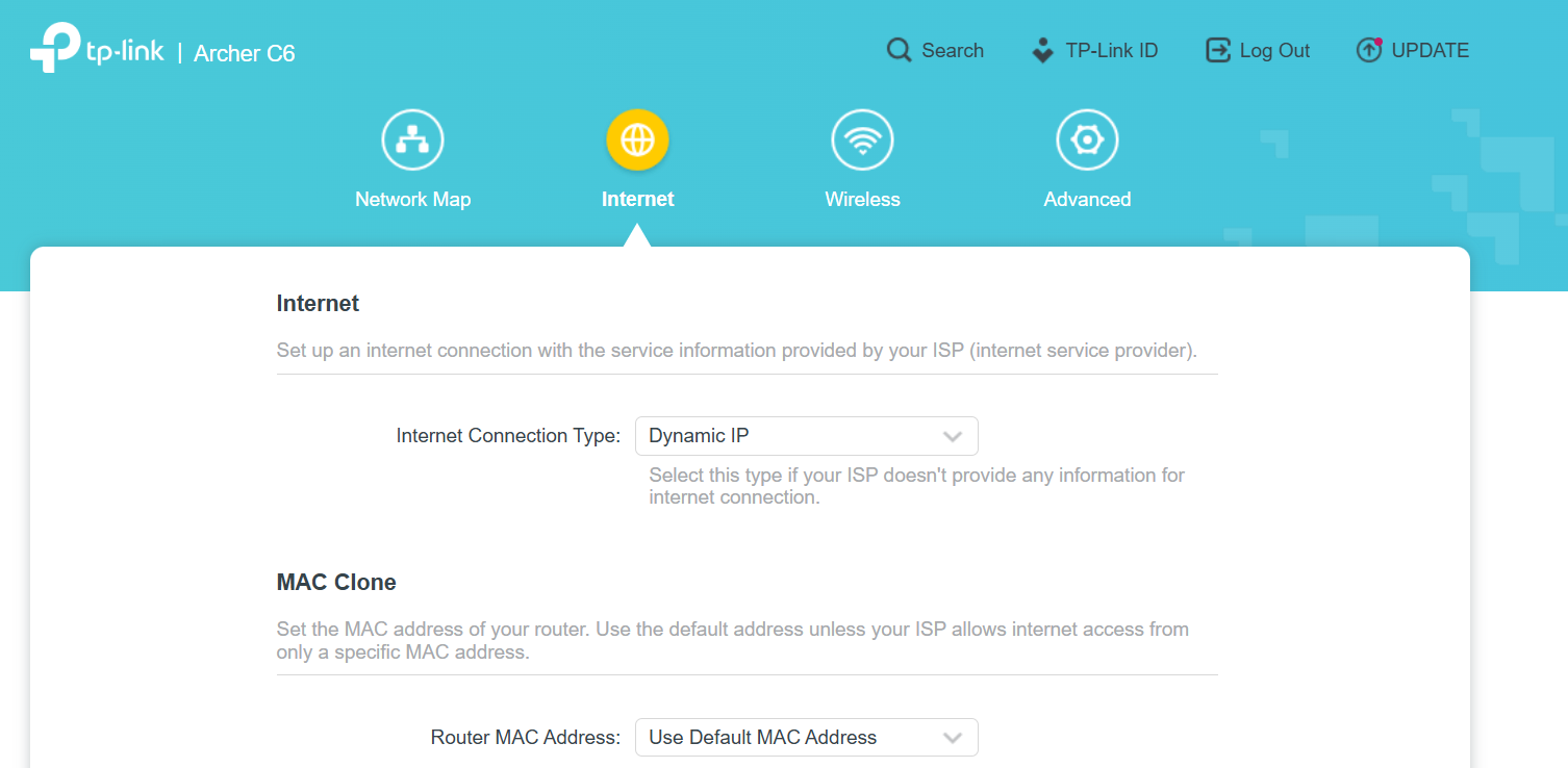
Internet Settings
Set the Internet Connection Type to Dynamic IP so it can receive an address from the WISP router or the host network via LAN.
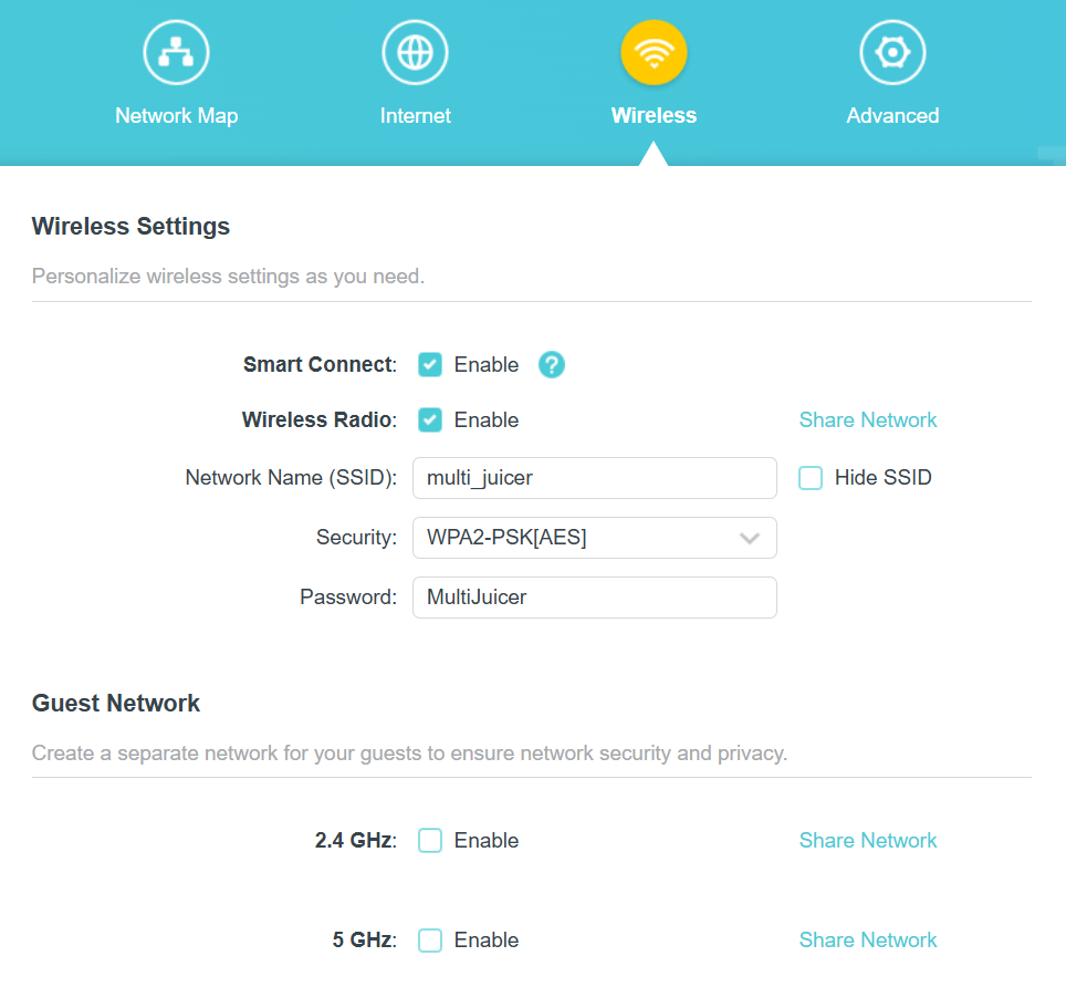
Wireless Settings
Configure the wireless network as follows:
-
SSID (Network Name):
multi_juicer -
Security:
WPA2-PSK[AES] -
Password:
MultiJuicer
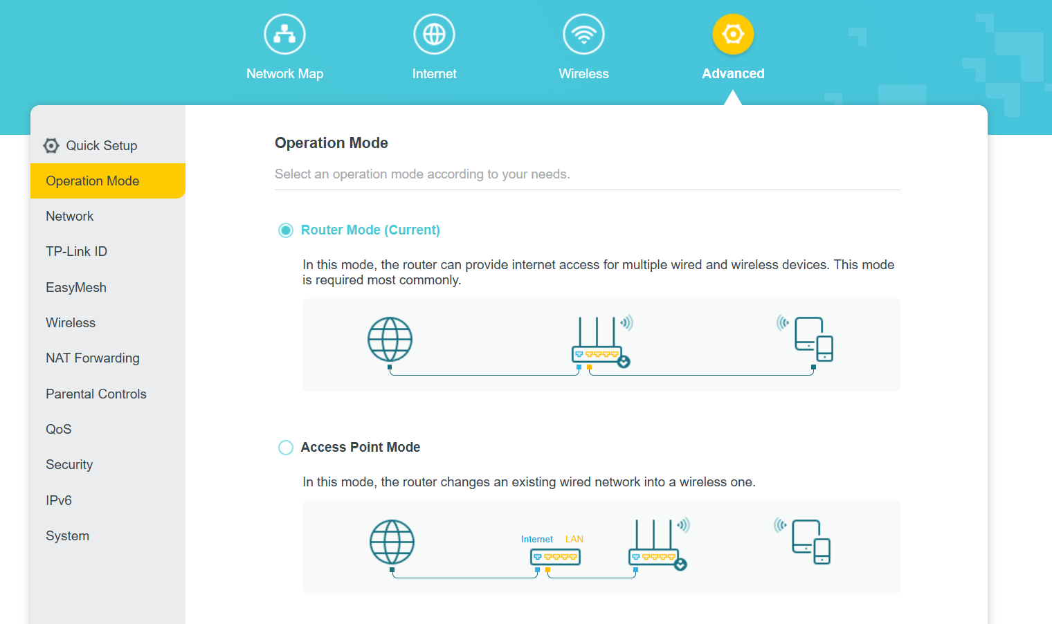
Operation Mode
The router must be set to Router Mode (default) to provide internet access and DHCP for all devices.
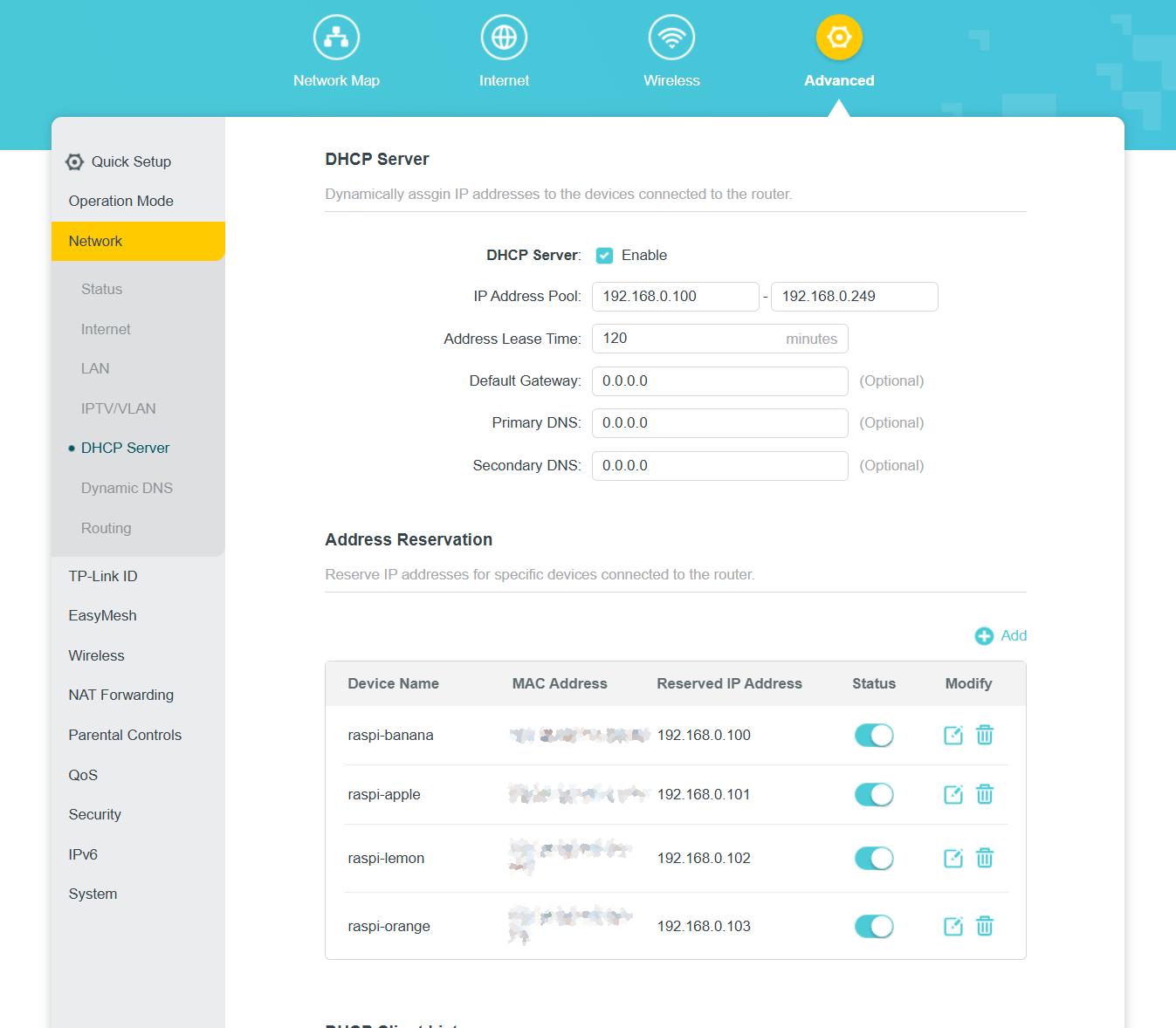
DHCP Server & Address Reservation
To ensure the Raspberry Pis always have the same IP address (required for k3s stability), use Address Reservation under the Advanced > Network > DHCP Server settings. Make sure the DHCP Server is enabled and configure the Address Reservation for each Raspberry Pi using their MAC addresses.